


Electromagnetic Flowmeter
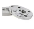
The material of this electromagnetic flowmeter includes ductile iron, carbon steel, stainless steel, brass, bronze, plastic. Its connection methods include flange connection, threaded connection, socket connection, etc. And its caliber: DN15-DN2000.
Standards: ISO, BS, EN, DIN, ASTM AISI, JIS.GBT etc.
Material: Ductile iron, carbon steel, stainless steel, brass, bronze, plastic
Interface: flange connection, threaded connection, socket connection, etc.
Diameter: DN15-DN2000
Surface anticorrosion: epoxy powder

Product Categories
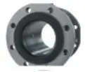
Electromagnetic flowmeter consists of sensor and converter. Sensor and converter installed together is called integrated electromagnetic flowmeter (see Figure 2), while sensor and converter installed separately is called separate electromagnetic flowmeter (see Figure 3).
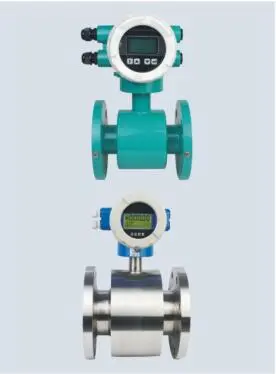
Figure 2 Integrated electromagnetic flowmeter
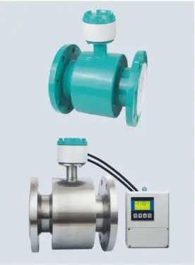
Figure 3 Separate electromagnetic flowmeter
Product performance characteristics
■ Wide application range
■ High accuracy level
■ Simple operation and maintenance
■ Proven technology
■ Designed to meet user applications
■ Flange connection methods that meet GB, DIN, ANSI, and JIS standards, and installation lengths that meet ISO standards.
■ Multiple material options
■ Multiple electrode material options
■ Removable electrode structure, online maintenance and replacement of electrodes.
■ Housing protection levels continue IP65, IP67, IP68
■ Separate converters are suitable for column or wall installation requirements
■ Multiple programming options
■ Multiple output/input signals
■ Multiple alarm functions: With self-test and self-diagnosis functions such as fluid empty pipe, magnetic auxiliary line, flow limit, upper/lower limit alarm, etc., it can eliminate erroneous measurements.
■ Multiple digital communications are optional
■ Suitable for explosion-proof applications
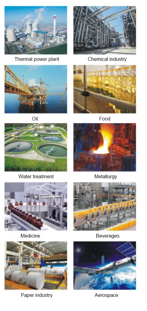
Application
After more than 20 years of experience accumulation and technology precipitation, the company has become a high-quality supplier in the domestic instrument industry. The company has a professional R&D and testing team, and independently designed, developed and manufactured domestic advanced water flow calibration devices and control systems. The company has won more than 100 invention patents and honorary police awards, including in the field of meters.
Used to measure the volume flow of conductive liquids and tight liquids in closed pipes, the products are widely used in pipe network zoning metering, large user trade settlement, independent metering area metering (community DMA), secondary water supply, petroleum, electricity, chemical industry, metallurgy, building materials, food, light industry, environmental protection, aerospace, tap water, municipal, sewage treatment and other industries.
Main parameters
■ Implementation standard: JB/T 9248-1999 "Electromagnetic Flowmeter"
■ Nominal diameter: DN15~DN3000 (mm); 1/2” ~24"
1/2”~24" (Inches).
(Inches).
■ Nominal pressure: 0.6MPa, 1.0MPa, 1.6MPa, 4.0Mpa (GB, DIN); 150lb., 300lb. (ANSI); JIS10K, JIS20K (JIS)
Note 1: For special pressure requirements, please consult the manufacturer.
■Accuracy: ±0.5% (optional ±0.2%)
■Conductivity of medium: ≥5 μS/cm
■Structural form: integrated type, suitable for caliber range DN15~DN1000
(mm); 1/2” ~24” (Inches);
Separate type, suitable for caliber range DN15~DN3000 (mm);
Note 2: In the case of separate type structure, the signal cable between the sensor and the converter is a special signal cable, model SMFE100.
Note 3: The connection length of the signal cable between the sensor and the converter should generally be ≤200m (650ft), > 200m (650ft) requires special ordering.
■Maximum flow rate: 15m/s (49ft/s)
■Ambient temperature: -25*C~+55*C (-13°F~+ 131°F)
■Relative humidity: 5%~90%
■Lining material:
|
Polytetrachloroethylene lining
Ceramic lining
Rubber lining |
Lining material |
Applicable caliber range |
Optional |
|
|
mm |
Inches |
|||
|
Soft rubber |
DN50~DN3000 |
2”~24° |
|
|
|
Hard rubber |
DN50~~DN3000 |
2”≈24” |
|
|
|
PTFE |
DN15~DN1000 |
1/2”≈24” |
|
|
|
Polyurethane |
DN15~DN300 |
1/2”≈12” |
|
|
|
PFA |
DN15~DN250 |
1/2”~10° |
Metal mesh reinforcement |
|
|
F46 |
DN15~DN250 |
1/2”~10° |
Metal mesh reinforcement |
|
|
Ceramics |
DN50~DN150 |
2”~6° |
|
|
■Electrode Material:
|
316L Stainless Steel Electrode
Stainless Steel Coated Tungsten Carbide Electrode |
Electrode Material: |
Applicable caliber range |
|
|
mm |
Inches |
||
|
316L Stainless Steel |
DN15~DN3000 |
1/2”~24° |
|
|
Hastelloy C-22 |
DN15~DN1000 |
1/2”~24° |
|
|
Hastelloy B-10 |
DN15~DN1000 |
1/2”~24 |
|
|
Titanium |
DN15~~DN600 |
1/2”~24 |
|
|
Tantalum |
DN15~DN600 |
1/2”~24 |
|
|
Platinum/lridium Alloy |
DN15~DN250 |
1/2“~10° |
|
|
Tungsten Coated Stainless Steel |
DN15~DN1000 |
1/2”~24 |
|
■ Liquid contact (grounding) and lining protection method:
|
Stainless steel flange |
Liquid contact (grounding) and lining protection |
Applicable caliber range |
|
|
mm |
Inches |
||
|
Body flange grounding |
DN15~DN3000 |
1/2”~24° |
|
|
Lining protection flange (grounding ring) |
DN15~DN250 |
1/2”~10° |
|
|
Grounding electrode |
DN15~DN1000 |
1/2”≈24” |
|
|
Inlet protection flange |
DN15~DN300 |
1/2”~12° |
|
■Maximum temperature of fluid medium: (determined by lining material and structure)
|
PTFE raw material
Natural rubber
Ceramic material |
Lining material |
Maximum temperature of fluid medium: (determined by lining material and structure) |
|||||
|
Conventional(A) |
Optional(B) |
Optional(C) |
|||||
|
|
℉ |
℃ |
℉ |
℃ |
℉ |
||
|
Soft rubber |
≤80 |
≤176 |
≤120 |
≤248 |
|
|
|
|
Hard rubber |
|
|
|||||
|
PTFE |
≤180 |
≤356 |
|||||
|
Polyurethane |
|
|
|
|
|||
|
PFA |
≤120 |
≤248 |
|
|
|||
|
F46 |
|
|
|
|
|||
|
Ceramics |
≤120 |
≤248 |
|
|
|||


■Protection level: IP65, IP67 (integrated structure only), IP68 (separated structure only).
■Explosion-proof certification: ExdibmbICT4Gb
■Power supply (optional): AC: 85VAC~265 VAC/45 Hz~63 Hz, power consumption ≤20VA; DC: 16VDC~36VDC, power consumption ≤16VA. Battery: 3.6VDC
(Note 4: Only accuracy ±0.5%, pulse output, RS485 are optional.)
■Display mode: 3-line LCD with backlight display
■Programming mode: key programming, infrared remote control programming, bus programming.
■Output signal (programmable):
1) Analog current output:
a) Current output signal: fully isolated 0~ 10mA/ 4~20mA.
b) Load resistance: 0~1.5k0 for 0~10mA; 0~7500 for 4~20mA.
c) Basic error: ±10μA is added to the basic error.
2) Frequency output:
The upper limit of the output frequency can be set within 1~5000Hz. The frequency output is a transistor collector open circuit output (OC gate) with photoelectric isolation, the external power supply is ≤36VDC, and the maximum collector current is 50mA when it is turned on. Optional relay output, external power supply is ≤36VDC, and the maximum collector current is ≤250mA when it is turned on.
3) Pulse output:
The upper limit of the output pulse can reach 5000cp/S. The pulse equivalent is defined as the volume flow represented by each pulse. The pulse equivalent can be selected as 0001L/p, 0.001L/P, 0.01L/p, 0.1L/p, 1.0L/p, 2L/p, 5L/p, 10L/p, 100L/p, 1m3/p, 10m3/p, 100 m3/p and 1000 m3/p. The pulse width can be selected as: automatic, 10ms, 20ms, 50ms, 100ms, 150ms, 200ms.250ms, 300ms, 350ms and 400ms. The pulse output is a transistor collector open circuit output with photoelectric isolation, the external power supply is ≤36V DC, and the maximum collector current is 50mA when it is turned on. Relay output is optional, the external power supply is ≤36VDC, and the maximum collector current is ≤250mA when it is turned on.
4) Alarm output:
Two transistor collector open circuit alarm outputs with photoelectric isolation. External power supply ≤36VDC, maximum collector current when on is 50mA. Optional relay output, external power supply ≤36VDC, maximum collector current when on is ≤250mA.
5) Digital communication interface: optional RS232, RS485, MODBUS, HART. Profibus-DP.
■Electrical isolation:
•The insulation voltage between analog input and analog output is not less than 500V;
•The insulation voltage between analog input and alarm power supply is not less than 500V;
•The insulation voltage between analog input and AC power supply is not less than 500V;
•The insulation voltage between analog output and AC power supply is not less than 500V;
•The insulation voltage between analog output and earth is not less than 500V;
•The insulation voltage between pulse output and AC power supply is not less than 500V;
•The insulation voltage between pulse output and earth is not less than 500V;
•The insulation voltage between alarm output and AC power supply is not less than 500V;
•The insulation voltage between alarm output and earth is not less than 500V.
Reference working conditions and error curve
According to the reference working conditions specified in JB/T 9248-1999:
■Ambient temperature: 20°C (68°F) ±2*C (±35.6°F)
■Relative humidity: 60%~70%
■Power supply: 220VAC±1%, 50Hz±1%
■Installation conditions: upstream straight pipe length>10XDN; downstream straight pipe length>5XDN. (Note 5: Based on the center of the electrode)
■Warm-up time: 30 minutes
■Analog output influence: pulse signal error plus ±0.1%
Error curve: (see Figure 4)
■Standard calibration (pulse output signal):
±0.5% of the indicated value (flow velocity>0.6m/s), or ±3mm/s (flow velocity≤0.6m/s), whichever is greater.
[±0.5% of the indicated value (flow velocity>1.97ft/s), or ±0.01 ft/s (flow velocity≤1.97ft/s), whichever is greater.]
■Optional calibration (pulse output signal):
±0.2% of the indicated value (flow velocity>1.0m/s), or ±2mm/s (flow velocity≤1.0m/s), whichever is greater.
[±0.2% of the indicated value (flow velocity>3.28ft/s), or ±0.006ft/s (flow velocity≤3.28ft/s), whichever is greater.]
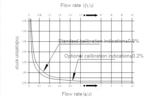
Figure 4 Flow meter error curve
Flow rate---flow rate comparison table (see Table 1)
|
Nominal diameter DN |
Full scale flow rate (m³/h) |
Full scale flow rate(US Gal/min) |
|||||
|
mm |
Inches |
v=0.3m/s |
V=1.0m/s |
V=15m/s |
y=1.0ft/s |
v=3.0ft/s |
v=49 ft/s |
|
(minimum) |
|
(maximum) |
(minimum) |
|
(maximum) |
||
|
15 |
½ |
0.1909 |
0.6362 |
9.543 |
0.612 |
1.836 |
29.99 |
|
20 |
¾ |
0.3393 |
1.131 |
16.96 |
1.377 |
4.131 |
67.47 |
|
25 |
1 |
0.5301 |
1.767 |
26.51 |
2.448 |
7.344 |
120 |
|
32 |
1.25 |
0.8686 |
2.895 |
43.43 |
3.825 |
11.47 |
187.4 |
|
40 |
1.5 |
1.357 |
4.524 |
67.86 |
5.508 |
16.52 |
269.9 |
|
50 |
2 |
2.121 |
7.069 |
106 |
9.792 |
29.38 |
479.8 |
|
65 |
2.5 |
3.584 |
11.95 |
179.2 |
15.3 |
45.9 |
749.7 |
|
80 |
3 |
5.429 |
18.1 |
271.4 |
22.03 |
66.1 |
1080 |
|
100 |
4 |
8.482 |
28.27 |
424.1 |
39.17 |
117.5 |
1919 |
|
125 |
5 |
13.25 |
44.18 |
662.7 |
61.2 |
183.6 |
2999 |
|
150 |
6 |
19.09 |
63.62 |
954.3 |
88.13 |
264.4 |
4318 |
|
200 |
8 |
33.93 |
113.1 |
1696 |
156.7 |
470 |
7677 |
|
250 |
10 |
53.01 |
176.7 |
2651 |
244.8 |
734.4 |
11995 |
|
300 |
12 |
76.34 |
254.5 |
3817 |
352.5 |
1058 |
17273 |
|
350 |
14 |
103.9 |
346.4 |
5195 |
479.8 |
1439 |
23511 |
|
400 |
16 |
135.7 |
452.4 |
6786 |
626.7 |
1880 |
30708 |
|
450 |
18 |
171.8 |
572.6 |
8588 |
793.2 |
2379 |
38864 |
|
500 |
20 |
212.1 |
706.9 |
10603 |
979.2 |
2938 |
47981 |
|
600 |
24 |
305.4 |
1018 |
15268 |
1410 |
4230 |
69092 |
|
700 |
28 |
415.6 |
1385 |
20782 |
1919 |
5758 |
94042 |
|
800 |
32 |
542.9 |
1810 |
27143 |
2507 |
7520 |
122831 |
|
900 |
36 |
687.1 |
2290 |
34353 |
3173 |
9518 |
155457 |
|
1000 |
40 |
848.2 |
2827 |
42412 |
3917 |
11750 |
191923 |
|
1200 |
48 |
1221 |
4072 |
61073 |
5640 |
16921 |
276369 |
|
1400 |
56 |
1663 |
5542 |
83127 |
7677 |
23031 |
376169 |
|
1600 |
64 |
2171 |
7238 |
108574 |
10027 |
30081 |
491322 |
|
1800 |
72 |
2748 |
9161 |
137414 |
12690 |
38071 |
621830 |
|
2000 |
80 |
3393 |
11310 |
169646 |
15667 |
47001 |
767691 |
|
2200 |
88 |
4105 |
13685 |
205272 |
18957 |
56872 |
928906 |
|
2400 |
96 |
4886 |
16286 |
244291 |
22561 |
67682 |
1105475 |
|
2600 |
104 |
5734 |
19113 |
286702 |
26478 |
79433 |
1297398 |
|
2800 |
112 |
6650 |
22167 |
332507 |
30708 |
92123 |
1504674 |
|
3000 |
120 |
7634 |
25447 |
381704 |
35251 |
105753 |
1727305 |
Note 6: Flow calculation in metric units:
Q(m3/h)= 0.00282744X D2 x V
Where: D--- Nominal diameter, mm.
V--- Flow rate, m/s.
Note 7: Flow calculation in imperial units:
Q(US Gal/min)=2.44799xD2X V
Where: --- Nominal diameter, inch.
V--- Flow rate, ft/s.
Hot Tags: Electromagnetic Flowmeter
Send Inquiry
Contact Info
-
Address
No. 112, Jiefang Road, Lixia District, Jinan City, Shandong Province, China
-
Tel
-
E-mail
Ready to take your water system project to the next level? Send an inquiry to Shandong Epoch Equipment Co., Ltd. and receive a personalized response from our team. We are here to help with all your water system needs. Let us be your trusted partner.


